 |
am3zzw00030461
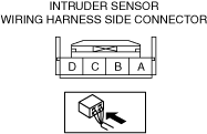
INTRUDER SENSOR INSPECTION
id091400517300
1. Disconnect the negative battery terminal. (See NEGATIVE BATTERY TERMINAL DISCONNECTION/CONNECTION [(E)].)
2. Remove the intruder sensor with the connector connected. (See INTRUDER SENSOR REMOVAL/INSTALLATION.)
3. Connect the negative battery terminal. (See NEGATIVE BATTERY TERMINAL DISCONNECTION/CONNECTION [(E)].)
4. Verify that the voltages of each of the terminals are as indicated in the terminal voltage table (reference).
Terminal Voltage Table (Reference)
am3zzw00030461
|
|
Terminal |
Signal name |
Connected to |
Measurement condition |
Voltage (V) |
Inspection item (s) |
|---|---|---|---|---|---|
|
A
|
Ground
|
Body ground
|
Under any condition
|
Approx. 0
|
• GND point
• Related wiring harness
|
|
B
|
—
|
—
|
—
|
—
|
—
|
|
C
|
DATA
|
Body control module (BCM)
|
Because this terminal is for communication, determination using terminal voltage inspection is not possible.
|
||
|
D
|
Power supply
|
• F50 15A fuse
• F27 25A fuse
|
Under any condition
|
B+
|
• F50 15A fuse
• F27 25A fuse
• Related wiring harness
|